
0
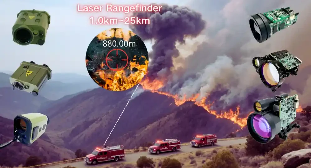
Laser Ranging Distance Limited? Divergence Angle vs. Target Size
Are you struggling to optimize your laser ranging distance when deploying rangefinder modules in the field?
- The emission power is high, yet the system consistently fails to detect distant UAVs or small target markers.
- Replacing the emitter with a higher-power laser yields negligible range improvement.
- Ranging distance varies drastically between day and night for the exact same physical target.
The underlying bottleneck in achieving maximum laser ranging distance is rarely insufficient laser power—it is the mismatch between the effective target reflection area and the beam divergence angle. This guide outlines three quantitative relationships to help engineering teams diagnose range limitations and optimize hardware selection.
I. Fundamental Physics: What Dictates Laser Ranging Distance?
Laser telemetry operates as a two-way energy transmission cycle. In determining effective laser ranging distance, the returned echo signal intensity Pr is quantified by the following relationship:
Pr ∝ (Pt × ρ × A_target) / (θ² × R⁴)
- Pt: Emission power
- ρ: Target surface reflectivity
- A_target: Effective target reflection area
- θ: Laser divergence angle (full angle, mrad)
- R: Ranging distance
Engineering Insights:
- Larger Area & Higher Reflectivity → Significantly extended ranging distance.
- Smaller Divergence Angle → Higher energy concentration, extended distance.
- R⁴ Power Attenuation → Echo signal decays exponentially over distance, posing a severe challenge for long-range systems.
Selection Mantra: Focus on Power for large surface targets; focus on Divergence Angle for small point targets.
II. Relationship 1: “Surface Target” vs. “Point Target”
Surface Target (Target Area >> Spot Size)
When the laser spot falls entirely within the physical boundaries of the target, target dimensions no longer limit echo power. Maximum range depends primarily on emitter power, optics transmission, and detector noise.
- Typical Scenarios: Concrete structures, storage tanks, terrain mapping, large commercial vessels.
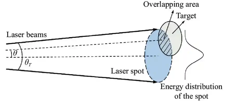
Point Target (Target Area << Spot Size)
The target captures only a fraction of the expanding laser beam energy. In point target laser ranging, the maximum achievable distance approximates:
R_max ∝ r_target / θ
- Smaller target radius r_target → Shorter maximum distance.
- Larger divergence angle θ → Rapid energy dissipation, shorter maximum distance.
Engineering Pain Point:
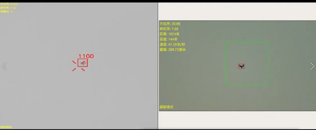
- You want to use a ranging module to measure a DJI Mavic UAV (size about 0.2m×0.3m) 2km away — this is a typical “point target” scenario.
- If the module’s divergence angle is 1 mrad, the spot diameter at 2km is about 2m, and the UAV only captures less than 1% of the energy. Therefore, even if the power is increased, the effect is very poor.
- It is necessary to prioritize reducing the divergence angle rather than simply increasing the power.
III. Relationship 2: Divergence Angle Controls Energy Density
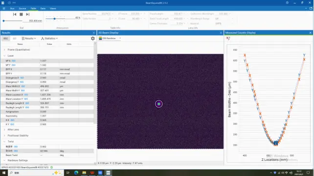
Beam Spot Diameter D ≈ L × θ (where L is distance).
When the divergence angle increases from 0.3 mrad to 1 mrad, the spot area expands by about 11 times at the same distance, and the energy density drops sharply.
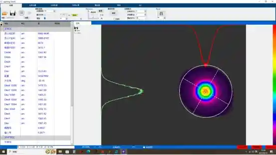
The size of the divergence angle affects the focusing ability of the laser beam and the spot size at a specific distance, which is a key performance indicator for many applications. The larger the emission angle, the larger the spot size at the same distance.
It can be known from the echo power formula:
Halving the divergence angle increases returned echo power by 400% (4×).
Recommended Divergence Angle Matrix
| Application Scenario | Recommended Divergence (θ) | Engineering Rationale |
|---|---|---|
| Ultra Long-Range Monitoring (>5km) | ≤ 0.3 mrad | Preserves energy density over long optical paths |
| Industrial Precision Inspection | ≤ 0.5 mrad | Concentrates energy on small mechanical features |
| Mobile Robotics & Commercial UAVs | 0.5 ~ 1.0 mrad | Balances dynamic target tracking with optical efficiency |
| Geospatial Surveying & Construction | 1.0 ~ 2.0 mrad | Eases beam alignment constraints |
IV. Relationship 3: Optimization Strategies Under Different Limits
Scenario A: Target is Much Larger than the Spot (Surface Target)
- The impact of divergence angle is minimal and can be appropriately relaxed (1 ~ 2 mrad).
- Ranging distance is primarily dictated by laser emission power and receiver optics aperture.
Scenario B: Target is Much Smaller than the Spot (Point Target)
- A narrow divergence angle must be prioritized (≤ 0.5 mrad).
- At this stage, boosting power alone cannot compensate for optical energy spilling past target boundaries.
Practical Optimization Steps:
- Measure or estimate the minimum effective dimensions and surface reflectivity (ρ) of the target.
- Define the required operational laser ranging distance (R).
- Calculate the required minimum energy density → back-calculate the maximum allowable divergence angle.
- Select the smallest possible divergence angle within cost, weight, and thermal limitations.
V. Common Misunderstandings & Pitfall Avoidance Guide
| Misunderstanding | Physical Reality & Fact |
|---|---|
| “Higher power always guarantees longer distance.” | For point targets, power increases yield diminishing returns; beam divergence angle is the primary system bottleneck. |
| “Smaller divergence angle is always better.” | Too narrow an angle makes target acquisition and aiming extremely difficult (especially on vibrating platforms). Balance is required. |
| “Ranging distance capability is identical across all targets.” | A 10-fold difference in reflectivity can cause a >3-fold change in ranging distance. Specification sheet “Max Distance” refers to large, high-reflectivity targets. |
| “It is ideal for the laser spot to completely cover the target.” | For point targets, a spot far larger than the target wastes energy into space; the spot should ideally be only slightly larger than the target. |
VI. Practical Selection: How to Choose NTRON Products
VI.I Application Scenario → Recommended 1535nm Laser Rangefinder Module Series
| Application Scenario | Target Profile | Recommended Model | Key Specifications & Advantages |
|---|---|---|---|
| Long-Range Cooperative Targets | >0.5m, >80% Reflectivity | Handheld Telescope | 0.4 mrad, Range ≥ 10km, Integrated GPS/Bluetooth |
| Long-Range Non-Cooperative Targets | 0.3 ~ 2m | NLM6000A Laser Rangefinder Module NLM7300A Laser Rangefinder NLM8000A Laser Ranging Module | 0.3 mrad ultra-narrow beam, Range 6 ~ 8km |
| Airborne Small Targets | 0.2 × 0.3m UAVs | NLM7000U 7km UAV Tracking | Lightweight (180g) UAV laser distance sensor optimized for small targets |
| Ultra-Lightweight Integration | AGVs, Portable Devices | NLM3000B 3km UAV Laser Ranging Module | Ultra-compact 17g, 24.6 × 15.4 × 30mm |
| Gimbal & Inspection Payloads | Vehicles, Personnel | Electro-Optical System Solutions | Tri-sensor integration (Visible + Thermal + 1535nm) |
| Field Surveying & Inspection | Infrastructure, Buildings | Handheld Telescope | 7× Optics, OLED display, IP67 ruggedized |
For high-precision sub-100m measurement (such as industrial part positioning), 650nm phase-shift rangefinder modules are recommended for millimeter-level accuracy.
VI.II Divergence Angle Quick-Calculation Formula
For point targets, the upper limit of the required maximum divergence angle is approximately:
θ_max ≈ (d_target / R) × k
(where k = 0.5 ~ 1.0 safety margin)
- Example: Target diameter 0.5m, required distance 2000m → θ_max ≈ (0.5 / 2000) × 1.0 = 0.25 mrad.
Selection Recommendation: NLM6000A (0.3 mrad) mounted on a stabilized platform.
VII. Technical Discussion & Engineering Support
Are you experiencing performance bottlenecks in your current optronic design? Leave a comment or reach out:
- What specific target dimensions and surface materials are you attempting to measure?
- What optical range limit are you currently encountering?
Our optics team can provide custom link budget simulations and divergence angle matching recommendations.
“Focus on Power for large targets; focus on Divergence Angle for small targets.” — The golden rule for laser telemetry selection.
VIII. Contact NTRON for Custom Link Budget Analysis
If your application requires optimizing maximum laser ranging distance beyond standard product specifications, provide the following constraints for a complimentary technical evaluation:
- Minimum target dimensions, surface reflectivity, and optical characteristics
- Maximum operational distance and atmospheric visibility conditions
- Weight limit, supply voltage, and allowable optical window aperture
- Operating temperature range and vibration/shock resistance thresholds
- Multi-sensor requirement (Visible light / Thermal imaging integration)
- Email: lizzy@ntronlaser.com
- Website: www.ntronl.com