0
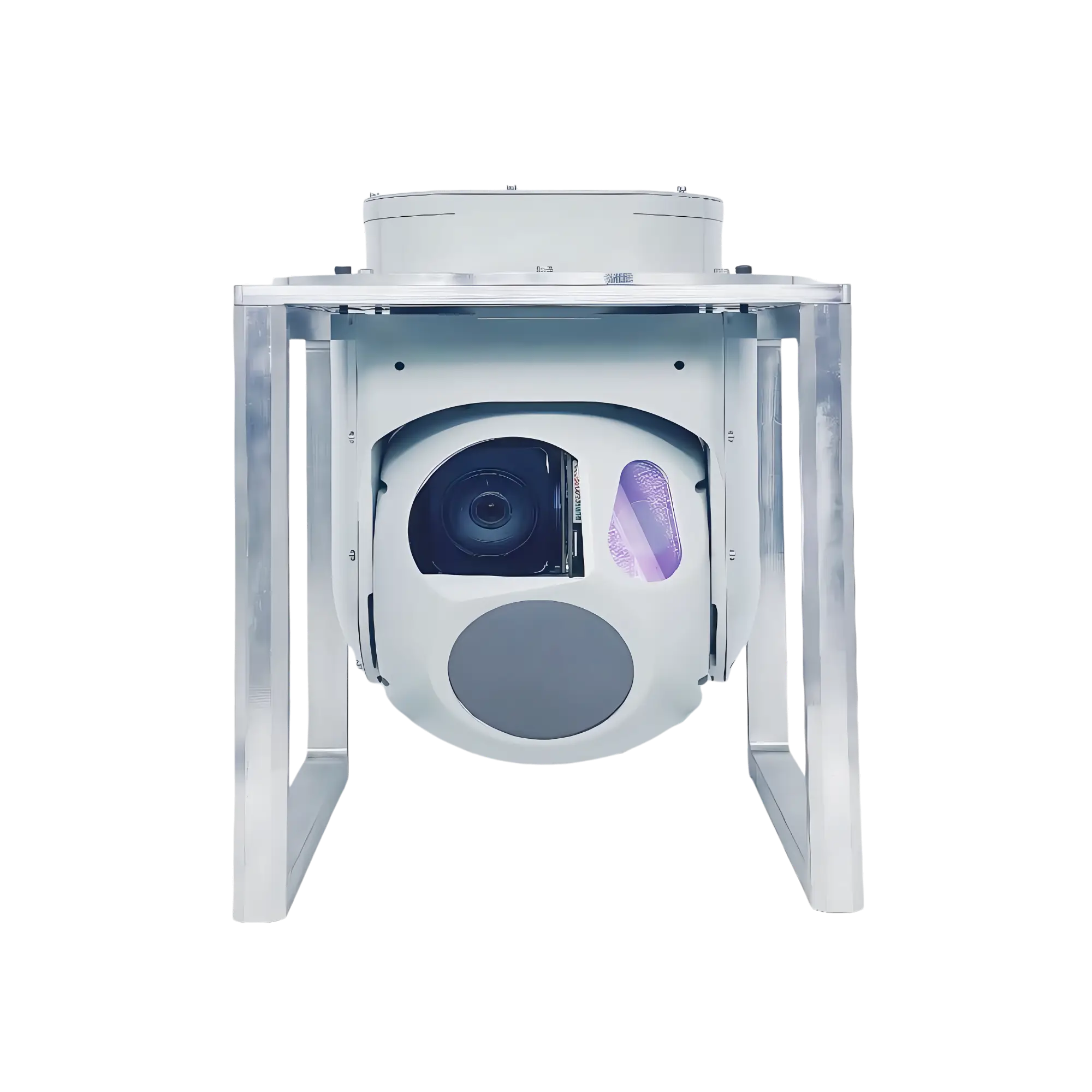
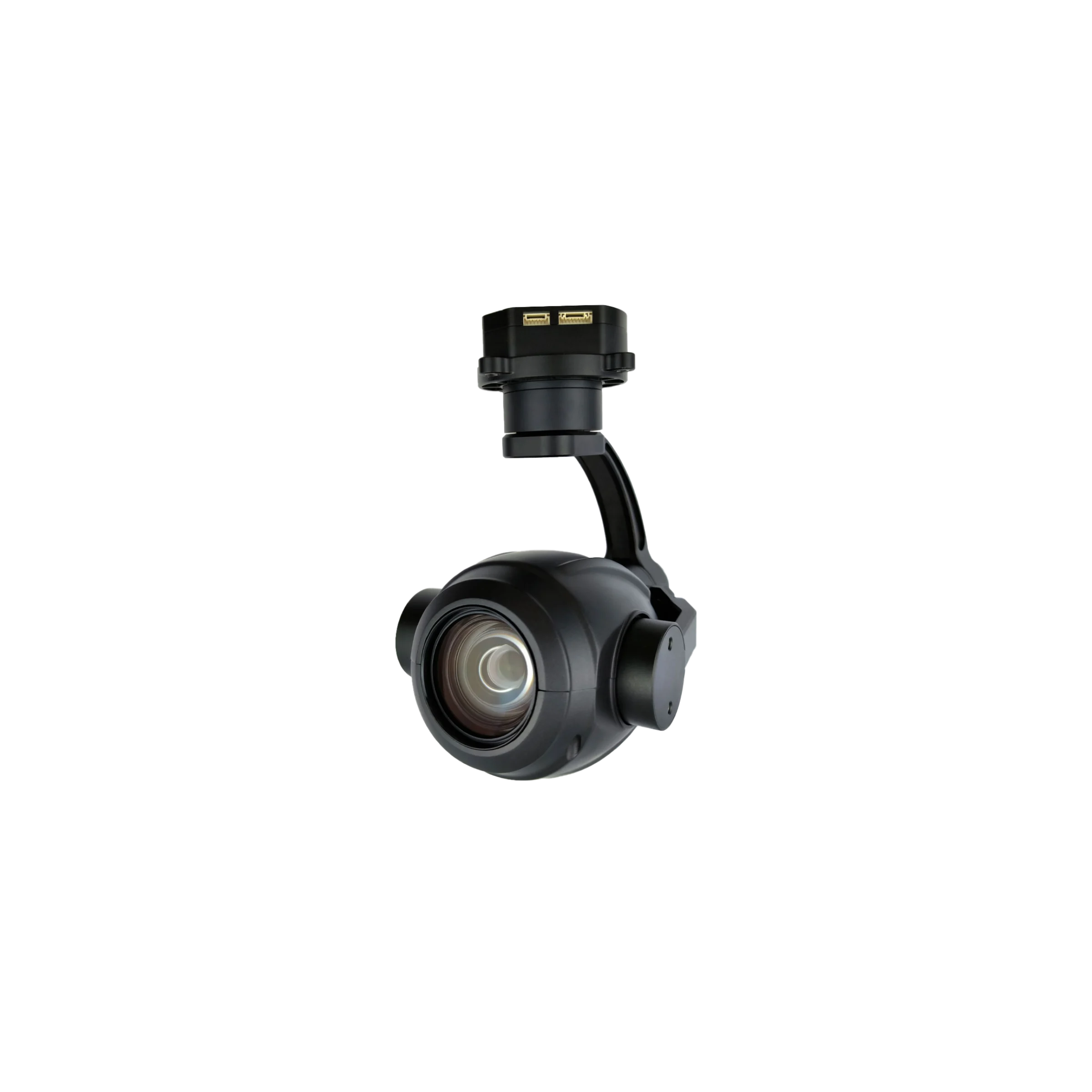
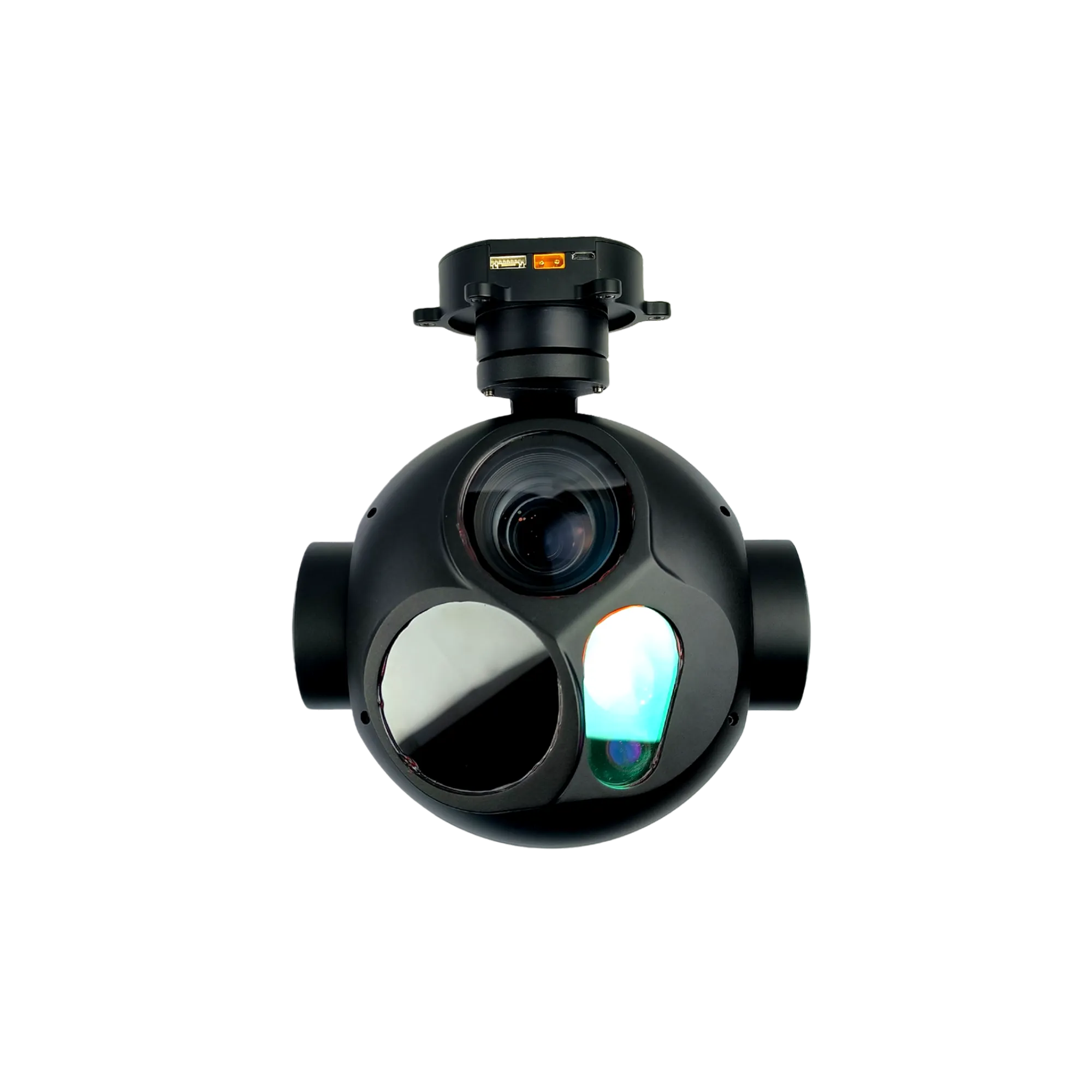
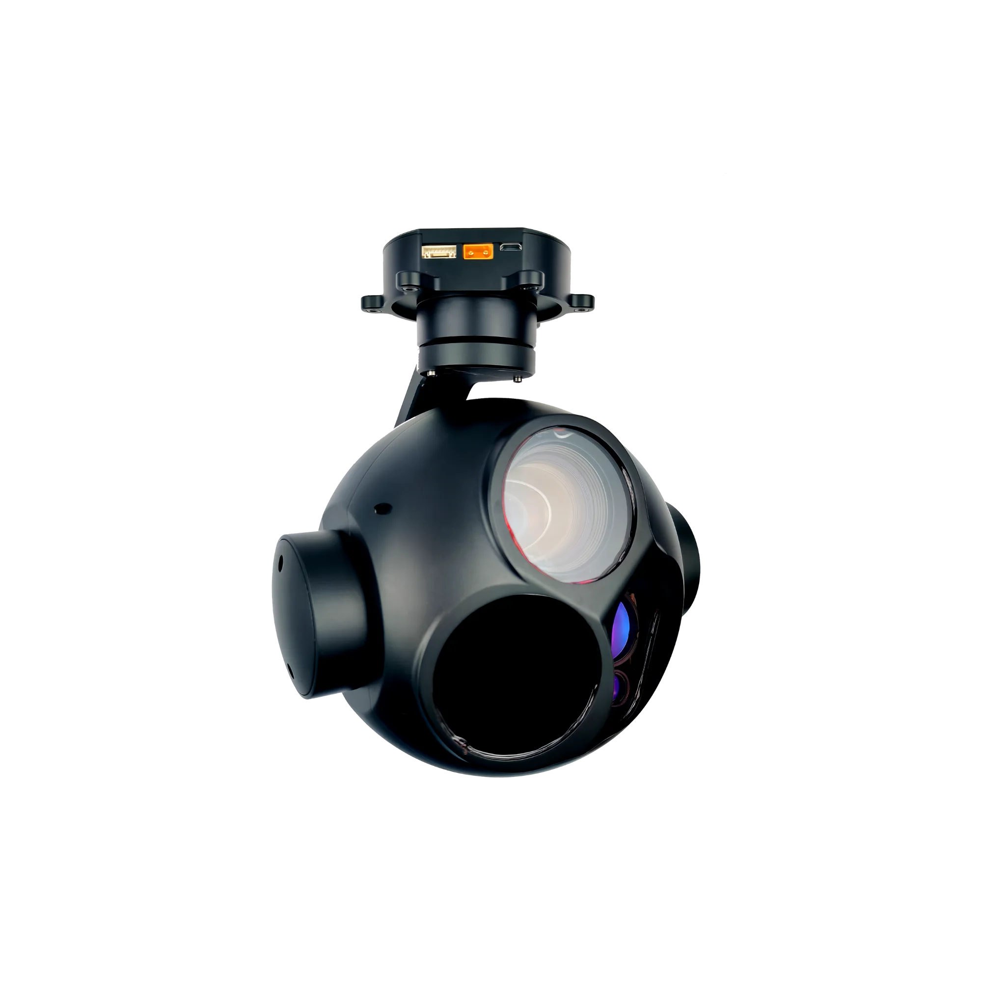
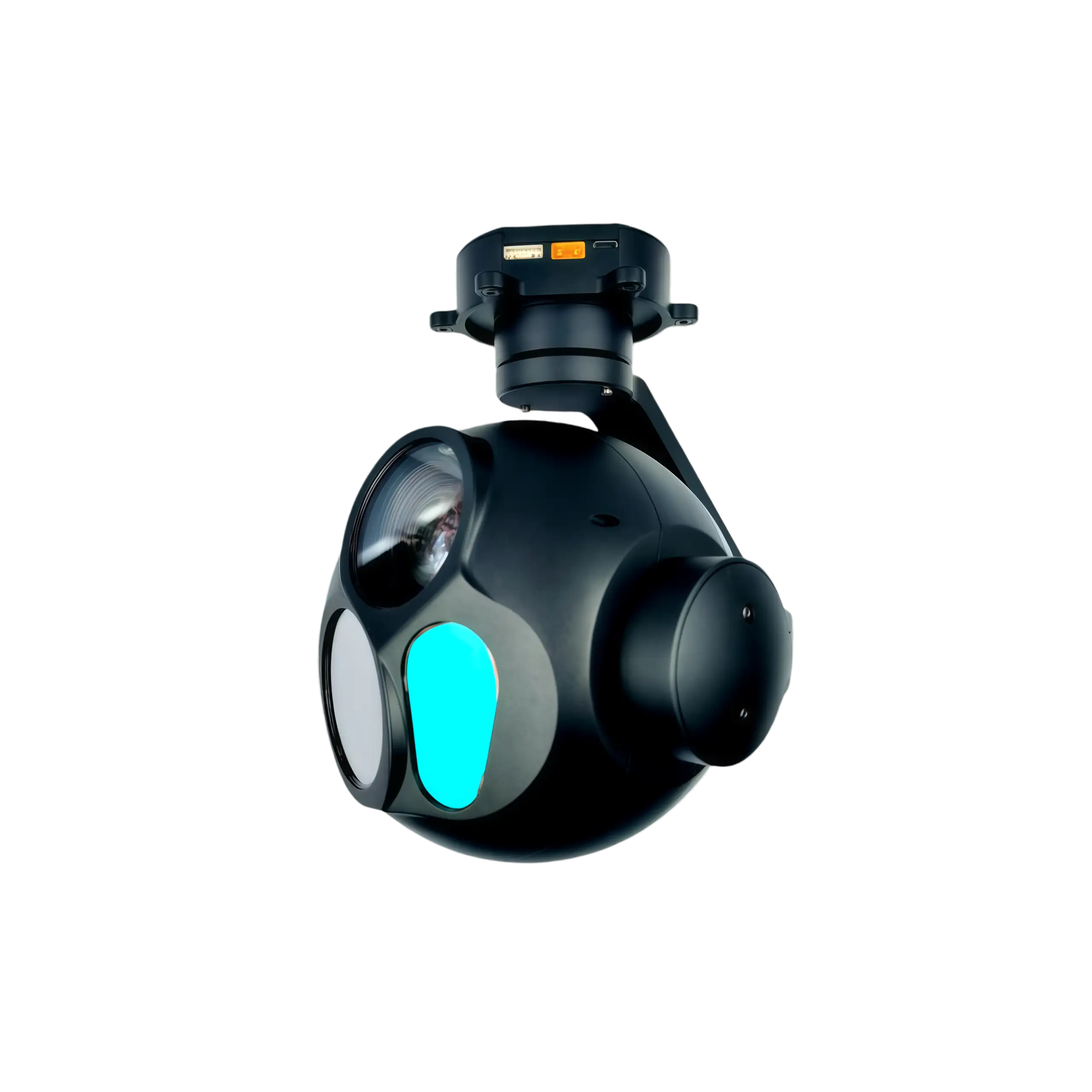
NTPOD305 Long Range Tracking Electro-Optical Pod
The Long Range Tracking Electro-Optical Pod is a 1580g, 3-axis FOC stabilized tri-sensor payload featuring a 270× hybrid zoom camera, a 640×512 LWIR core, and a 5000m laser rangefinder with ±0.02° jitter accuracy.
- Optical Sensors: 2MP 30× optical zoom (f=4.5–135mm) and 12µm 640×512 uncooled VOx infrared microbolometer.
- Laser Rangefinder: Class 1 eye-safe 1535nm telemetry covering 50m to 5000m with ±1m precision.
- Physical Dimensions: Total form factor of W165mm × D169mm × H195mm with IP54/IP67 ingress protection.
- Control Integration: RTSP 1080P30FPS video streaming via network IP with concurrent TTL, S.BUS, and PWM control.
NTPOD305 Long Range Tracking Electro-Optical Pod Profile
The NTPOD305 long range tracking electro-optical pod provides a specialized solution for severe industrial environmental mapping by integrating triple-sensor capabilities into a highly integrated 3-axis stabilized gimbal. The optomechanical assembly synchronizes a 2MP continuous optical zoom visible camera, a 35mm uncooled vanadium oxide (VOx) infrared core, and a 5,000-meter eye-safe laser rangefinder within a structured engineering framework measuring W165mm × D169mm × H195mm. Driven by high-resolution optical encoder feedback and a closed-loop field-oriented control (FOC) scheme, the platform eliminates high-frequency carrier angular drift to secure a critical pitch and roll jitter precision threshold of ±0.02° and horizontal yaw stability down to ±0.03°.
Real-time localization and target categorization are handled natively via built-in neural network tracking loops. The internal tracking layer identifies target sizes from a minimum 16×16 pixel envelope up to a 256×256 pixel field, processing human profiles and vehicle vectors across complex flight profiles at speeds reaching 50 pixels per frame. The rugged, industrial-grade outer structural housing limits total system mass to 1580±20g while complying with IP54 and IP67 protection classifications, securing stable dual-channel microSD recording and low-latency RTSP 1080P video streaming over integrated IP networks during sustained outdoor deployments.
NTPOD305 270× Hybrid Zoom, 640×512 Thermal & 5000m Laser Rangefinder Primary Functions
- Dual-Channel Synchronized Video Output: Integrates a 2MP 30× optical zoom module (270× hybrid zoom via 9× digital scaling) paired alongside a 640×512 12µm thermal camera core to process concurrent real-time picture-in-picture (PIP) streaming and 10 optional false color patterns.
- High-Precision FOC Encoder Stabilization: Employs brush-free FOC servo motors driving a 3-axis platform to achieve active gyro stabilization of ±0.02° (pitch/roll) and ±0.03° (yaw) across 360° continuous horizontal pan rotation limits.
- Onboard Edge AI Target Tracking: Executes localized image segmentation algorithms to detect up to 100 targets concurrently, maintaining high-speed identification of vehicles and pedestrians with up to 2 seconds of visual occlusion recovery.
- Industrial-Grade Laser Rangefinding: Features an eye-safe 1535±10nm Class 1 laser transceiver returning telemetry coordinates from 50m to 5000m with an absolute precision index of ±1m, enabling automatic distance overlays onto network video metadata.
- Multi-Protocol Control Interface: Synchronizes commands via 3.3V LVTTL UART serial ports, hardware S.BUS links, PWM signals via decoder boards, and network IP connections, writing backup assets onto dual onboard FAT32 microSD slots (32GB to 256GB).
NTPOD305 Electro Optical Pod Technical Specifications
| Gimbal Platform & Mechanical System Parameters | |
| Operational Voltage Input | DC 12V to 26.2V |
| System Power Dissipation | Dynamic 10W |
| Structural Mass Assembly | 1580 ± 20g |
| Physical Form Factor Dimensions | W165mm × D169mm × H195mm |
| Ingress Protection Rating | IP54 / IP67 Industrial Standard |
| Control Method Interfaces | SBUS, PWM Signal Control (Decoder board), UART, IP network or TTL serial |
| Local Data Storage Slot | Onboard MicroSD (TF Card), 32GB to 256GB, Class 10 or above, FAT32 Format |
| Thermal Operational Window | -10°C to +55°C / 20% to 80% RH |
| Storage Thermal Limits | -20°C to +60°C / 20% to 95% RH |
| Pitch and Roll Jitter Angle | ±0.02° |
| Horizontal Jitter Angle | ±0.03° |
| Mechanical Pitch Angle Range | -30° to +120° |
| Mechanical Roll Angle Range | -45° to +45° |
| Mechanical Yaw Angle Range | 360 Degree Continuous Rotation |
| Communication Baud Rate | 115200 |
| Visible Light Electro-Optical Tracking Sensor Specifications | |
| Sensor Matrix Resolution | 2MP Pixels |
| Optical Zoom Configuration | 30× Optical Zoom (270× Hybrid Zoom with 9× Digital Zoom) |
| Optical Focal Length Range | f = 4.5 to 135 mm ± 5% |
| Focusing Time Latency | Real time fast focusing, focusing time < 1s |
| Field of View (FOV) Diagonally | D : WIDE 67.8°±5% TELE 2.77°±5% |
| Field of View (FOV) Horizontally | H : WIDE 59.8°±5% TELE 2.34°±5% |
| Field of View (FOV) Vertically | V : WIDE 40.5°±5% TELE 1.48°±5% |
| Zoom Drive Mechanism | electric zoom and continuously adjustable |
| Image Capture Storage Format | Image: jpeg format (multipixel can be choosed) |
| Video Recording Interface Format | Video: H264 format; 1080P30FPS |
| Video Transmission Stream | IP/HDMI output; RTSP 1080P video stream, Local TF 1080P recording |
| Uncooled Thermal Imaging Electro-Optical Sensor Payload | |
| Sensor Matrix Resolution | 640×512 pixel |
| Pixel Architecture Pitch | 12µm |
| Detector Core Architecture | Uncooled infrared microbolometer camera |
| Spectral Bandwidth Operation | 8~14µm |
| Thermal Sensitivity (NETD) | ≤50mk @ F1.0 |
| Optical Lens Focal Length | 35mm Lens |
| Thermal Field of View (FOV) | FOV: 12.52° × 10.03° |
| Temperature Measurement Scope | -20°C~ 150°C, extendable to 100°C~550°C |
| Temperature Measurement Precision | ±3°C or ±3% (whichever is greater) |
| Thermal Analysis Configuration | Supports global temperature measurement; optional full-pixel temperature save function |
| Image Enhancements & Correction | Adaptive dynamic range compression AGC, Non-uniformity correction NUC, EE enhance |
| Color Palette Matrix | Black heat, white heat, pseudo color (≥8 kinds) |
| Integrated Laser Rangefinder Module Telemetry Parameters | |
| Laser Operational Wavelength | 1535 ± 10nm |
| Laser Safety Classification | Safety Classification Class 1 |
| Module Operational Blind Zone | Do not use the camera to shoot the object on less than 50m distance |
| Rangefinding Measurement Envelope | 50–5000m |
| Telemetry Precision Threshold | Accuracy ±1m |
| Ranging Resolution Index | Ranging resolution ≤ 40m |
| Target Recognition & Tracking Circuit Parameters | |
| Minimum Tracking Target Area | 16×16 pixels |
| Maximum Tracking Target Area | 256×256 pixels |
| Maximum Allowable Occlusion Interval | 2 seconds |
| Maximum Processing Tracking Speed | 50 Pixel/Frame max |
| Concurrent Target Detection Capacity | 100 targets max |
| Edge AI Classification Categories | Human and Vehicle |
| Minimum Detection Target Area | 32×32 pixels |
| Video Processing Architecture | RTSP 1080P30FPS Picture in picture output |
NTPOD305 Tri-Sensor Gimbal Interconnect Architecture & Full-Functional Signal Routing Blueprint
The NTPOD305 features an integrated technical tracking hub comprising a main 8PIN external layout, power routing, and low-latency digital streaming components. Ensure the incoming voltage complies strictly with the DC 12V to 26.2V operational limit to prevent board degradation.
| PIN No. | Interface Type | Signal Definition | Functional Overview |
| PIN 1 | Power Interface | GND | System Ground |
| PIN 2 | Power Interface | 5V | +5V Power Output |
| PIN 3 | Communication Interface | RxD4 | TTL Serial Port Receiving (3.3V LVTTL UART) |
| PIN 4 | Communication Interface | TxD4 | TTL Serial Port Sending (3.3V LVTTL UART) |
| PIN 5 | Communication Interface | DB- | Network Interface B- Line |
| PIN 6 | Communication Interface | DB+ | Network Interface B+ Line |
| PIN 7 | Communication Interface | DA- | Network Interface A- Line |
| PIN 8 | Communication Interface | DA+ | Network Interface A+ Line |
*Note: Device may change structure due to product update. Please connect to NTRON to get newest datasheet.
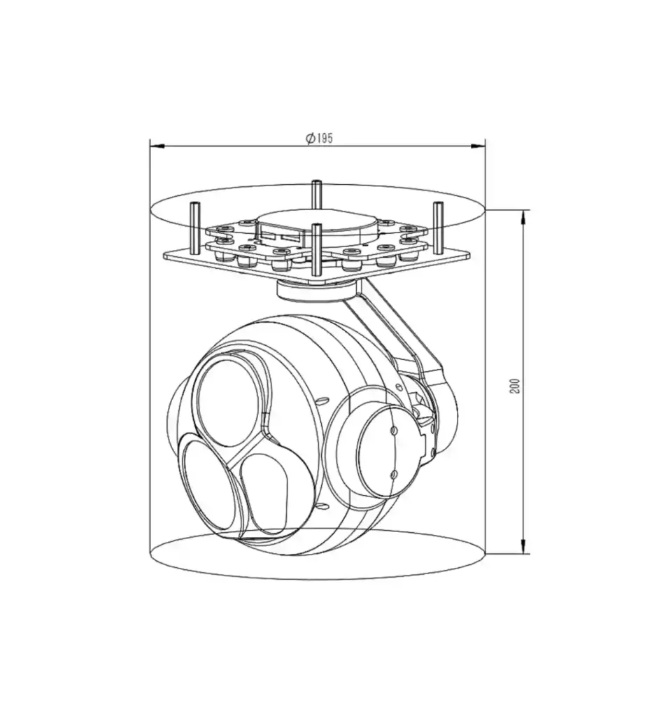
NTPOD305 3-Axis Gyro-Stabilized Enclosure Schematic & Mechanical Footprint Profile
The mechanical drawing details the precise spatial layout and structural envelope of the NTPOD305 3-light camera payload. Designed with built-in vibration shock absorption arrays, the upper installation interface has a clearance profile bounding cylinder requirements of Φ195mm and a mechanical housing height of 200mm to secure uninterrupted 360-degree rotation tracking sweeps.
UAV & Airborne Tri-Sensor Gyro Gimbal Target Industry Applications
- UAV Infrastructure Inspection: Deploys a high-fidelity 2MP optical tracking matrix and active 3-axis gyro stabilization to streamline automated macro-structural health surveys and line sagging measurements.
- Substation Thermal Infrared Diagnostics: Leverages the 640×512 VOx microbolometer core to diagnose critical surface overheating anomalies and transformer structural defects from -20°C to 550°C without field shutdowns.
- Linear Corridor Utility Patrols: Employs continuous 360° horizontal yaw panning and dual-channel RTSP 1080P networking to monitor remote infrastructure routing networks and isolated industrial boundaries.
- Precision Distance Mapping Validation: Interfaces a 5000m eye-safe laser rangefinder module to supply absolute target geometry metadata directly into structural inspection data workflows.
- Automated Asset Defect Inventorying: Directs an onboard Edge AI processing core to automatically tag, monitor, and log up to 100 industrial infrastructure profiles concurrently across low-visibility environments.
Engineering Integration Note: This stabilized long range tracking electro-optical pod interfaces natively with our manufacturing infrastructure. For downstream low-light observation pairings or alternative dual-channel visible sensor configurations, please review our high-magnification NTPOD207 Starlight Night Vision Gimbal Camera portfolio or examine the ultra-lightweight NTPOD80A Commercial-Grade Micro Pod parameters to receive updated API and SDK schemas.
To cross-examine professional three-axis FOC platforms with a modular quick-disconnect hardware infrastructure, review the technical specifications of our NTPOD125B Electro-Optical Pod or the continuous continuous-zoom NTPOD115 Dual-Sensor Optical Layout.